In a Nutshell
Dynamic instrumentation uses inertial sensors, which requires to perform either single or double integration of signals. Having excellent linearity and no threshold, their resolution is essentially limited by their inherent noise, which In turn depends prominently on two parameters: firstly, the signal conditioner inherent noise and secondly, the selected lower end of the frequency bandwidth.
While the choice of the starting frequency depends on the problem at hand, the knowledge of the conditioning electronics inherent noise is indispensable, and basing estimates on the overall (wideband) noise level can lead to significant in error in the estimation of the instrument noise. It is therefore mandatory to either obtain more information from the vendor (with all due caution), or better,to run simple tests such as the corrected difference or the dummy sensor test as described above.
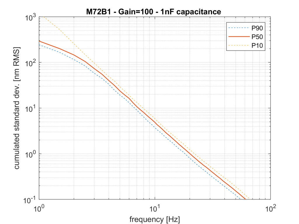
Once the spectral content of the noise is known, it is a matter of simple, spreadsheet -type calculation to obtain the required estimate. The most practical chart to be produced looks like the one below: it features the best estimate (i.e., median value, or 50% probability of exceedance) of the displacement standard deviation, as a function of the lower most frequency.

On Figure 6, one can readily read the required lower cutoff frequency (high-pass) to be used in order to guarantee that the setup total noise will not exceed a given value. For example, setting 10nm RMS as an acceptable noise level, one simply needs to (mentally) draw a horizontal line at 10nm and reading the intersection with the P50 curve. In this case, the intersection occurs at 7Hz, so this is the lower frequency limit to be used. It remains to see if this is compatible with the overall system performance, but generally mechanical resonances are well above this value, so even a ‘basic’ setup already offers interesting performances.
What’s next?
We have covered the basics. However, in future posts, I will cover two important aspects pertaining to the question, namely:
- environment effects, and
- enhanced performance using specific hardware: (low-noise electronics, high-sensitivity sensors)
In the meantime, all questions are very welcome.
References
[1] Collette – ATS/Note/2011/001 (TECH) 2011-01-05 – Review of sensors for low frequency seismic vibration measurement
https://cds.cern.ch/record/1322403/files/CERN-ATS-Note-2011-001-TECH.pdf
[2] Bruel and Kjaer, Model 2635 datasheet, last retrieved as of Feb 2023 under: https://www.bksv.com/-/media/literature/Product-Data/bp0099.ashx
[3] Rubiola, Lectures on Instruments, http://rubiola.org/
[4] Laboratoire Souterrain à Bas Bruit, (LSBB) https://lsbb.cnrs.fr/
[5] Virtins technologies Charge mode sensors Accessories https://virtins.com/Piezo-Sensors.shtml
[6] MMF(Metra Mess- und Frequenztechnik ) https://www.mmf.de/pdf/4-1.pdf
